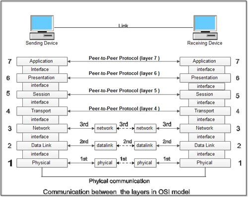
The OSI 7 Layers are :
(Layer 1) Physical
(Layer 2) Data Link
(Layer 3) Network
(Layer 4) Transport
(Layer 5) Session
(Layer 6) Presentation
(Layer 7) Application
Based on the project scenario, the data will travel from the student’s home network to UTeM facilities. The UTeM’s students will try to access the Ulearn System located in the UTeM network facilities. In the following section, it will explain the data interaction between layers in the OSI model.
Application Layer (Layer 7)
Presentation Layer (Layer 6)
The presentation layer deals with the syntax and semantics of the information exchanged between two systems. Presentation layer performs data compression for multimedia data before transmitting, as the length of multimedia data is very big and much bandwidth will be required to transmit it over media, this data is compressed into small packets and at the receiver’s end, it will be decompressed to get the original length of data in its own format. At the student's side, it receives the data from the application layer and performs data encryption and compression to it. At the Ulearn System server side, it receives the data from the transport layer and performs data translation, decryption, and uncompressed data.
Session Layer (Layer 5)
Session layer mainly helps in setting up, closing and managing the connection in the network whenever two devices get connected, a session is created, which is terminated as soon the connection is no longer required. The termination of the session is important to avoid the unnecessary wastage of resources. In other words, the session layer performs session management. The session layer enables the devices to send and receive the data by establishing connections and also terminates the connection after the data transfer. It mainly performs authentication and authorization for establishing a secure connection in the network. The session layer synchronises the student's computer and Ulearn System server. It adds various checkpoints with the data to synchronise data at the student's computer side and Ulearn System server's side. In case of any crash or transfer failure, the data transmission can be resumed from the last checkpoint. There is no need to retransfer the whole data.
Transport Layer (Layer 4)
Transport layer responsible for the process-to-process delivery of the data. It performs flow and error control in the data for its proper transmission. The transport layer controls the reliability of communication through various functionalities. At the student's side, the transport layer receives the data from the upper layer and performs segmentation. The source and destination port numbers are also included in the header file of the data before forwarding it to the network layer. At the Ulearn System server's side, the transport layer performs the reassembly and sequencing of data. It reads the port number of the data from the header file and then directs it towards the proper application.
Network Layer (Layer 3)
The Network layer performs the transmission of data from one computer to another in different networks. This layer may not be so beneficial if we are transmitting the data in the same network. The network layer performs logical addressing (IP addressing) of the data. The source and destination IP addresses are included in the data header file by the network layer. The data is in the form of packets in this layer. At the student's side, the network layer breaks the data segments received from the upper layer into smaller units, called data packets. Similarly, at the Ulearn System server's side, it reassembles the data packets into segments for the upper layer, i.e., the transport layer. Routers are mainly used in the network layer for routing purposes. Some of the protocols that are mostly used in this layer are Open Shortest Path First (OSPF), Border Gateway Protocol (BGP), Intermediate System to Intermediate System (IS-IS) and so on.
Data Link Layer (Layer 2)
The Data-Link Layer performs the physical addressing of data. Physical addressing is the process of adding the physical(MAC) address to the data. Media Access Control (MAC) Address is a 48-bit alpha-numeric number that is embedded in a Network Interface Card (NIC) by the manufacturer. In other words, the data-link layer is embedded as software in the NIC which provides a means for data transfer from one computer to another via local media. Thus, the data-link layer facilitates the transmission of data within the same network only. The source and destination MAC addresses are included in the data header file by the data-link layer. At the student's side, it receives the data in the form of packets from the network layer and converts it into smaller forms, called the data frame. At the Ulearn System server's side, it converts the data frame into packets for the network layer.
Physical Layer (Layer 1)
The physical layer is the lowest layer in the OSI model. This layer is responsible for the actual physical connection between the devices and transmitting individual bits or signals from one node to the next. The signal will be generated depending upon the transmission medium. The output signal from physical hardware will be a light signal for optical fibre cable, and radio signal for air as a transmission medium. At the Ulearn System server's side, it will convert the bitstreams into frames to be passed to the data-link layer.
Network Components
Network components comprise both physical parts as well as the software required for installing computer networks, both at UTeM network facilities and at student’s homes.
Physical Layer
At the first layer which is the physical layer, the component that will be required is cables, Wi-Fi, repeaters and hubs. Network cable is also known as data cable or Ethernet cable which is a wired cable used to connect a device to the internet or to other devices like computer, printers and so on. The cables serve the purpose of taking bits from one end and taking them out to the other end. For the Wi-Fi, it solely exists to carry ones and zeros from one computer to the next. Then, the repeaters can simply amplify signals from one end out to the other end.
Data Link Layer
At the second layer, the required component is the Network Interface Card (NIC) and switches. Switches are devices which facilitate communication within a network meaning if the two hosts are connected via the switch, the switch is what’s going to help traffic move along to accomplish the hop. Moreover, switches also allow us to connect many devices.
Network Layer
The required component in the network layer is routers, hosts and anything with an IP address. Router is the device that used to connect a LAN with an internet connection. When we have two distinct networks (LANs) or want to share a single internet connection to multiple computers, we use a Router. The protocol in this layer is Internet Protocol (IP), Internet Control Message Protocol (ICMP), Address Resolution Protocol (ARP) and Reverse Address Resolution Protocol (RARP).
Transport Layer
Firewall is the security component that will be used in the transport layer. Firewall is used for a security mechanism which can monitor and filter incoming and outgoing network traffic based on an organization's previously established security policies. The protocol in this layer is Transmission Control Protocol (TCP), User Datagram Protocol (UDP).
Session Layer
At the session layer, the component will be used as a gateway. The gateway will translate one protocol into the other. A router is a special case of a gateway. Gateways also known as protocol converters which can operate at any network layer. The protocol in this layer is File Transfer Protocol (FTP), Hypertext Transfer Protocol (HTTP), Simple Mail Transfer Protocol (SMTP), Domain Name System (DNS), Technology in Finance Immersion Programme (TFIP) and WEB.
Presentation Layer and Application Layer
Components in these two layers are also the gateway and firewall. But in the application layer, it will end with devices like PC’s, phones and servers.
Comments
Post a Comment